Gas Turbine Inlet Air Filtration: Why Filter Selection Matters
Gas Turbine Fundamentals: Why Inlet Air Quality Is Everything
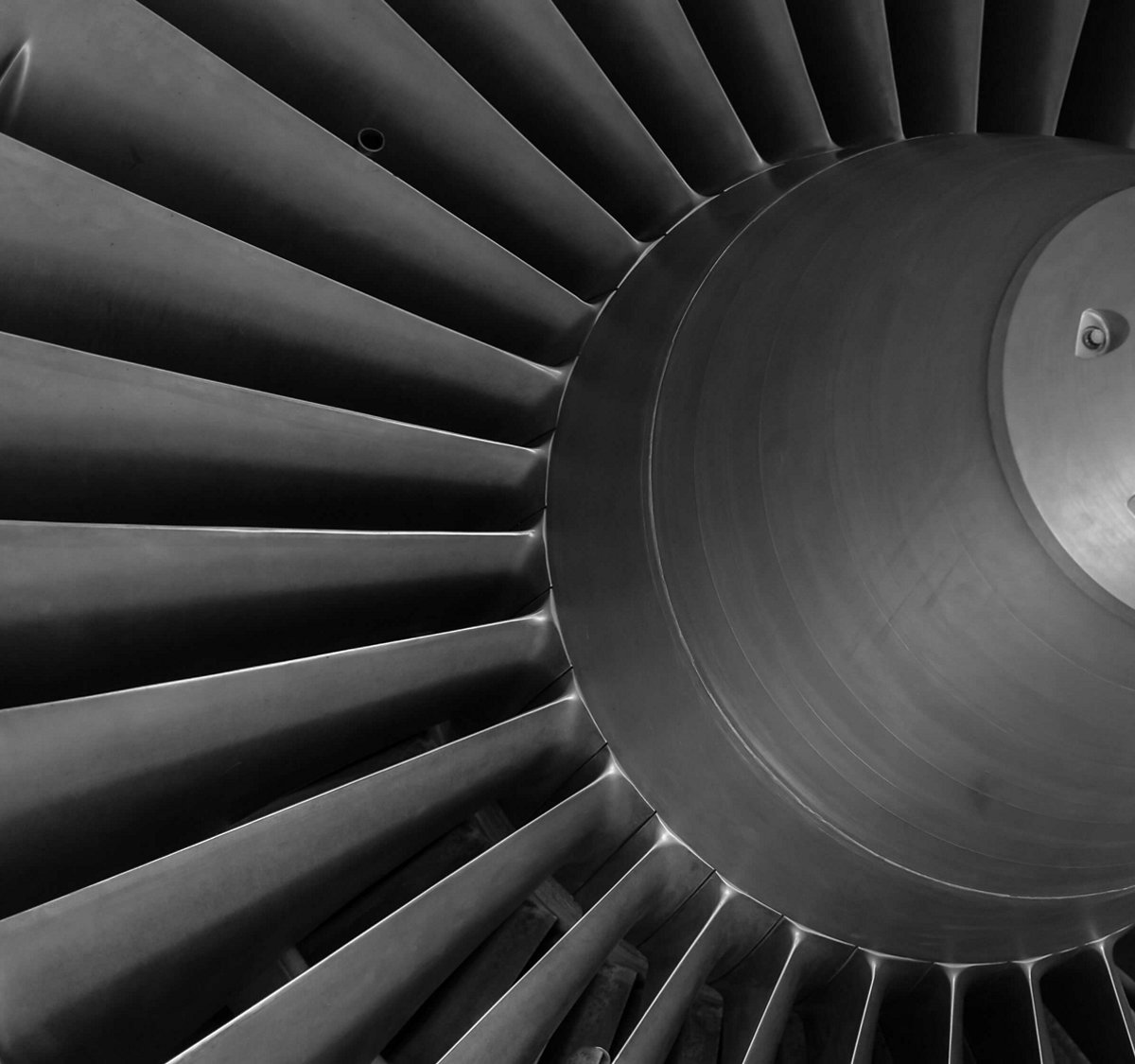
A gas turbine is an air-breathing machine. It ingests enormous volumes of ambient air — a 100 MW class industrial gas turbine processes approximately 500 to 700 kg of air per second — compresses it, mixes it with fuel, combusts the mixture, and expands the hot gas through a turbine section to generate mechanical power. The air entering the compressor inlet passes directly over the compressor blades, through the combustion chamber, and over the turbine blades. Every particle, salt crystal, droplet, and chemical contaminant in that air has the potential to damage the turbine's internal components.
The relationship between inlet air quality and turbine performance is direct and quantifiable. ISO 2314, the international standard for gas turbine acceptance tests, specifies that turbine output and heat rate are measured at defined inlet conditions — and that deviation from those conditions (including air cleanliness) must be accounted for in performance calculations. In practice, a gas turbine operating with degraded inlet filtration — or in an environment with high ambient contamination — will experience measurable reductions in power output, thermal efficiency, and component life compared to operation with clean, properly filtered inlet air.
The financial stakes are significant. A 1% reduction in gas turbine efficiency for a 100 MW unit operating at 70% capacity factor and a fuel cost of INR 15 per kWh of thermal input translates to approximately INR 9 crore per year in additional fuel cost. A compressor wash forced by fouling costs 4 to 8 hours of downtime plus the washing chemicals and labour. A blade replacement due to erosion or corrosion can cost INR 5 crore to INR 15 crore in parts alone, plus the revenue lost during the unplanned outage. The inlet air filtration system — typically 1% to 2% of the total turbine package cost — is the primary defence against all of these degradation mechanisms.
Contamination Types: What's in Indian Air and Why It Matters
The contaminants in ambient air that affect gas turbines can be categorised into four groups: particulate matter (dust, sand, pollen, insects), salt (sodium chloride and other marine salts), moisture (rain, fog, humidity), and chemical aerosols (industrial emissions, hydrocarbon vapours). Each creates a different degradation mechanism, and the severity varies dramatically by location. India, with its diverse geography and climate, presents a uniquely challenging range of contamination profiles.
Coastal locations — Chennai, Mumbai, Visakhapatnam, and the Gujarat coast — face high salt aerosol concentrations. Sodium chloride is the primary concern because it is both corrosive and hygroscopic. Salt particles deposited on compressor blades absorb moisture from the compressed air, creating a chloride-rich electrolyte film that attacks the nickel-based superalloys and protective coatings of the turbine hot section. Salt-induced corrosion is accelerated at the elevated temperatures in the combustor and turbine — a phenomenon known as hot corrosion, which can destroy turbine blade coatings in hundreds of operating hours if salt ingestion is not controlled.
Desert and arid locations — Rajasthan, Gujarat interior, and parts of Karnataka — face high particulate loads from wind-borne dust and sand. The mineral composition of Indian desert dust (primarily silica, alumina, and calcium compounds) makes it highly erosive. When ingested by the compressor, these particles abrade the leading edges and surfaces of the compressor blades, roughening the aerodynamic profiles and reducing compressor efficiency. Unlike fouling (which is recoverable by washing), erosion damage to compressor blades is permanent — the material removed by abrasion cannot be restored, and the blade must eventually be replaced.
Blade Degradation: Fouling, Erosion, and Corrosion
The three primary degradation mechanisms affecting gas turbine blades are fouling, erosion, and corrosion. Understanding the distinction is important because each mechanism has different implications for filter selection and maintenance strategy.
Fouling is the accumulation of fine particles and contaminants on compressor blade surfaces. The deposited material roughens the blade surface, disrupts the aerodynamic boundary layer, and reduces compressor efficiency. Fouling is recoverable — an online or offline compressor wash with demineralised water and a cleaning agent removes the deposits and restores most of the lost performance. However, frequent washing has its own costs (water, chemicals, downtime for offline washes) and is not a substitute for effective inlet filtration. A turbine with poor inlet filtration may require weekly offline washes, while one with properly specified filtration may operate for 3,000 to 5,000 hours between washes.
Erosion is the removal of blade material by the impact of hard particles. Erosion damage is not recoverable — once material is removed from a blade, the only remedy is blade refurbishment (re-coating and re-profiling, which is expensive and limited by minimum wall thickness) or blade replacement. Erosion is primarily caused by particles larger than 10 µm — sand, mineral dust, and heavy industrial particulate. The severity of erosion depends on particle size, hardness, concentration, and impact velocity (which increases with compressor tip speed).
Corrosion — particularly hot corrosion in the turbine section — is caused by chemical contaminants, primarily sodium and potassium salts, vanadium, and lead. These elements, when ingested with the inlet air or present in the fuel, form low-melting-point compounds (sodium sulphate, vanadium pentoxide) that attack the protective oxide layers on turbine blades at operating temperatures of 850°C to 1,300°C. The most insidious aspect of hot corrosion is that it occurs below the surface of the protective coating, undermining the coating adhesion and leading to spalling and accelerated base metal attack.
Filter Classes and Standards: ISO 16890 and Gas Turbine Practice
Gas turbine inlet air filters are classified according to their particle removal efficiency, measured by standardised test methods. The current international standard for general air filter testing is ISO 16890, which replaced the older EN 779 standard in 2018. ISO 16890 classifies filters by their efficiency at removing particles in three size fractions: ePM1 (particles ≤ 1 µm), ePM2.5 (particles ≤ 2.5 µm), and ePM10 (particles ≤ 10 µm). A filter rated ePM1 70%, for example, removes at least 70% of particles smaller than 1 µm from the air stream.
In gas turbine practice, the filter train typically consists of two or three stages. The first stage (pre-filter) is a coarse filter — typically ePM10 50% to 80% (equivalent to the old G4 or M5 class) — that captures large particles, insects, seeds, and debris. This filter protects the downstream fine filters from rapid loading and extends their service life. The second stage (final filter) is a high-efficiency filter — typically ePM1 50% to 80% (equivalent to F7 to F9) — that captures the fine particles responsible for fouling, erosion, and corrosion. In coastal or high-contamination environments, a third stage — a moisture separator (mist eliminator) or a coalescent filter — may be added to remove water droplets and salt aerosol.
The ASHRAE 52.2 standard, widely used in North America, provides an alternative classification system based on Minimum Efficiency Reporting Value (MERV). MERV ratings range from 1 (least efficient) to 20 (most efficient). For gas turbine applications, final filters in the MERV 13 to MERV 16 range are typical, depending on the contamination environment. Mann+Hummel gas turbine filters are tested and rated to both ISO 16890 and ASHRAE 52.2, providing the data needed for specification and comparison regardless of which standard the turbine OEM or owner references.
Typical Gas Turbine Inlet Filter Train Configuration
The design of a gas turbine inlet filter system involves several key decisions: the number of filtration stages, the filter media type and efficiency rating, the filter element configuration (panel, bag, cylindrical, or cassette), the need for moisture separation, and the choice between static (non-cleaning) and self-cleaning (pulse-jet) configurations. Each decision is driven by the specific contamination profile of the site, the turbine OEM's recommendations, and the operator's maintenance philosophy.
A typical two-stage static filter system for an inland location with moderate dust levels might use a pre-filter panel (ePM10 60%, synthetic media, 2-inch depth) followed by a final filter bag or rigid pocket filter (ePM1 60%, micro-glass fibre media, V-bank configuration). The pre-filter is replaced every 3 to 6 months, and the final filter every 12 to 24 months, based on differential pressure or calendar time. This configuration provides adequate protection for most inland gas turbine installations in India.
For coastal locations, the filter train must additionally address salt aerosol and moisture. A three-stage configuration is common: weather louvers and a coarse pre-filter for rain and large debris, a moisture separator stage (vane-type or mesh-type) to remove water droplets and dissolved salt, and a high-efficiency final filter (ePM1 70% or higher) to capture fine dry salt particles. In some coastal installations, a coalescent filter — which captures fine mist and sub-micron droplets by inertial impaction and diffusion — is added between the moisture separator and the final filter to provide additional protection against salt aerosol ingestion.
Self-Cleaning Pulse-Jet Systems vs. Static Filter Panels
In environments with very high dust loading — desert locations, cement plant surroundings, or sites near mining operations — static filters may load and reach their maximum differential pressure in days or weeks rather than months. For these applications, self-cleaning pulse-jet filter systems are preferred. In a pulse-jet system, cylindrical or cartridge filters are arranged in a filter house. When the differential pressure across a filter element exceeds a setpoint, a pulse of compressed air is directed through the element from the clean side, dislodging the accumulated dust from the outer surface. The dust falls into a hopper and is removed by a screw conveyor or vacuum system.
Pulse-jet systems have higher capital cost than static systems but dramatically lower filter replacement cost and maintenance labour. A static filter system at a dusty site might consume 200 to 400 filter elements per year; a pulse-jet system at the same site may operate for 3 to 5 years on the same set of cartridges, with only periodic cartridge inspection and replacement. Mann+Hummel manufactures cylindrical filter cartridges for pulse-jet gas turbine intake systems, using pleated polyester or cellulose-polyester composite media with PTFE membrane or nano-fibre surface treatment for enhanced dust release and low stable pressure drop.
Mann+Hummel Gas Turbine Filter Range
Mann+Hummel's gas turbine filtration portfolio covers the full range of filter elements and configurations used in gas turbine inlet systems worldwide. The product range includes panel pre-filters in standard and custom sizes, bag filters (pocket filters) in synthetic and glass fibre media, rigid V-bank final filters for low-pressure-drop high-efficiency applications, cylindrical cartridge filters for pulse-jet self-cleaning systems, and moisture separator elements. All products are manufactured to the dimensional and performance standards required by the major gas turbine OEMs, including GE, Siemens Energy, Mitsubishi Power, and Solar Turbines.
The key performance parameters for a gas turbine inlet filter are separation efficiency (measured at the relevant particle sizes), initial pressure drop, dust holding capacity (the amount of dust the filter can hold before reaching its maximum pressure drop), and mechanical integrity (resistance to moisture, temperature cycling, and pulse cleaning). Mann+Hummel filters are designed to optimise the trade-off between efficiency and pressure drop — higher efficiency filters tend to have higher pressure drop, and every Pascal of additional inlet pressure drop reduces turbine power output by approximately 0.05% to 0.1%. For a 100 MW turbine, this means that an unnecessarily high pressure drop of 500 Pa (versus a well-designed system at 250 Pa) costs approximately 250 kW to 1,000 kW of continuous power output.
Pressure Drop vs. Efficiency: The Power Output Trade-Off
The relationship between inlet filter pressure drop and gas turbine power output is one of the most important considerations in filter selection. Every gas turbine has a specified maximum allowable inlet pressure drop — typically 1,000 to 2,500 Pa for the complete inlet system (filter house, ducting, silencer, and trash screen). Of this budget, the filter elements typically account for 250 to 800 Pa at clean condition and 500 to 1,500 Pa at the change-out condition (maximum loaded pressure drop).
A filter that achieves high efficiency but at the cost of excessive pressure drop may cost more in lost power output than the value of the contaminants it removes. Conversely, a filter with very low pressure drop but poor fine-particle efficiency may allow fouling and corrosion that costs far more than the pressure drop saving. The optimal filter selection minimises total operating cost: the sum of pressure drop power loss, filter replacement cost, compressor washing cost, and blade degradation cost over the service interval.
Mann+Hummel optimises this trade-off through advanced media technology. The use of nano-fibre surface coatings on filter media, for example, provides high sub-micron particle capture efficiency (ePM1 70% or higher) while maintaining a low initial pressure drop (150 to 200 Pa for a final filter element). The nano-fibre layer captures fine particles on the surface of the media rather than within the media depth, which also enables more effective pulse-jet cleaning and extends the service life of the filter element in self-cleaning systems.
Compressor Washing: Online vs. Offline
Even with well-specified inlet filtration, some contamination will reach the compressor over time — no filter system achieves 100% removal of all particle sizes. Compressor washing is the complementary maintenance practice that removes accumulated deposits and restores compressor aerodynamic performance. There are two approaches: online washing and offline washing.
Online washing is performed while the turbine is running at load. A water-detergent solution is injected into the compressor inlet through spray nozzles, wetting the blade surfaces and dissolving or loosening accumulated deposits. The wash water and dissolved contaminants are carried through the compressor and combustor and exit with the exhaust gas. Online washing is a relatively quick procedure (10 to 15 minutes) and can be performed daily or every few days without shutting down the turbine. However, it is less effective at removing heavy or baked-on deposits than offline washing.
Offline washing requires the turbine to be shut down and cooled. A larger volume of wash solution is injected at low compressor speed (cranking speed), allowed to soak for a defined period, and then rinsed with clean water. The turbine is then accelerated to operating speed and returned to service. Offline washing is more thorough than online washing and can recover more of the lost performance, but it requires 4 to 8 hours of downtime — a significant cost for a peaking or baseload unit. The combination of effective inlet filtration (to minimise the rate of fouling) and a disciplined online/offline wash programme is the standard practice for maintaining gas turbine performance.
Indian Power Sector Context: Where Gas Turbines Operate
Gas turbines in India operate in a range of applications: utility-scale combined cycle power plants (typically 100 to 500 MW), open cycle peaking stations, captive power plants for industrial facilities (refineries, petrochemical complexes, steel plants), and cogeneration plants providing both power and process steam. The major gas turbine fleets are concentrated in Gujarat (NTPC Kawas, Essar, Reliance), Maharashtra (ONGC, Ratnagiri Gas), Andhra Pradesh/Telangana (NTPC Ramagundam, GMR Kamalanga), Tamil Nadu (TANGEDCO, various captive plants), and Karnataka (KPCL Raichur, various captive plants).
Each location presents a different contamination profile that should drive the inlet filtration specification. Coastal plants in Gujarat and Tamil Nadu face salt aerosol as the primary concern and require moisture separation and high-efficiency final filtration. Inland plants in Karnataka and Telangana face dust and industrial aerosol and may benefit from self-cleaning pulse-jet systems. Plants in industrial corridors — Chennai's Manali petrochemical complex, Pune's manufacturing belt — face mixed contamination including both particulate and chemical aerosols. The filter specification should be tailored to the specific site, not defaulted to a generic "one size fits all" configuration.
Maintenance Intervals and Procurement in Indian Power Sector
Gas turbine inlet filter replacement in Indian power plants typically follows either a calendar-based or a condition-based schedule. Calendar-based replacement changes pre-filters every 3 to 6 months and final filters every 12 to 24 months, regardless of measured pressure drop. Condition-based replacement monitors differential pressure across each filter stage continuously and triggers replacement when the pressure drop reaches a predefined limit. Condition-based replacement is generally more cost-effective, as it avoids premature replacement of filters that have not reached their useful life, but it requires reliable pressure differential instrumentation and a maintenance management system to track and act on the data.
Procurement of gas turbine inlet filters in Indian power plants is typically handled by the plant's materials management department, with technical specification input from the operations or maintenance engineering team. For NTPC and state DISCOM-owned plants, procurement follows Central or State Government procurement rules, which may require open tendering for orders above a threshold value. For private sector plants, procurement is more flexible but often driven by lowest-cost sourcing rather than optimised total cost of ownership. Mann+Hummel filters, with their combination of high efficiency, low pressure drop, and long service life, offer a compelling total cost proposition even when the per-element price is higher than commodity alternatives.
Filter disposal is an emerging consideration. Used gas turbine inlet filters contain accumulated particulate matter, which may include heavy metals and other regulated contaminants depending on the operating environment. Indian environmental regulations (Hazardous and Other Wastes Management Rules, 2016) require proper characterisation and disposal of waste that may be classified as hazardous. Mann+Hummel filter elements are designed for ease of disposal, with materials that can be segregated (metal frames, synthetic media, adhesives) for appropriate waste handling.
Contact Arvi Fluid Systems for Gas Turbine Filtration
Arvi Fluid Systems is the authorized distributor of Mann+Hummel industrial filtration products in Karnataka, Tamil Nadu, Kerala, and Pondicherry. We support gas turbine operators with filter selection based on site-specific contamination assessment, cross-referencing from existing OEM or aftermarket filter specifications, and supply of the full range of Mann+Hummel gas turbine inlet filter elements. Whether you are specifying filters for a new turbine installation or seeking to optimise filtration performance on an existing plant, our technical team can help. Contact Arvi Fluid Systems to discuss your gas turbine filtration requirements.